
Fig. 2.
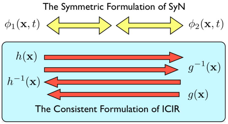
The symmetric normalization method is represented, at top, by its two components, φ1 and φ2, meeting at the middle of the normalization domain. Note that each sub-path may be traversed either from the middle to the end or from an end to the middle. Alternatively, the ICIR method is shown in a schematic at the bottom panel of the figure. The correspondence defining vector fields associated with ICIR are called h and g. In ICIR, all four deformation fields overlap in time and may, in fact, be different from each other. The inverse of h may not be its true inverse. Further, the inverse of h may not be equivalent to g.