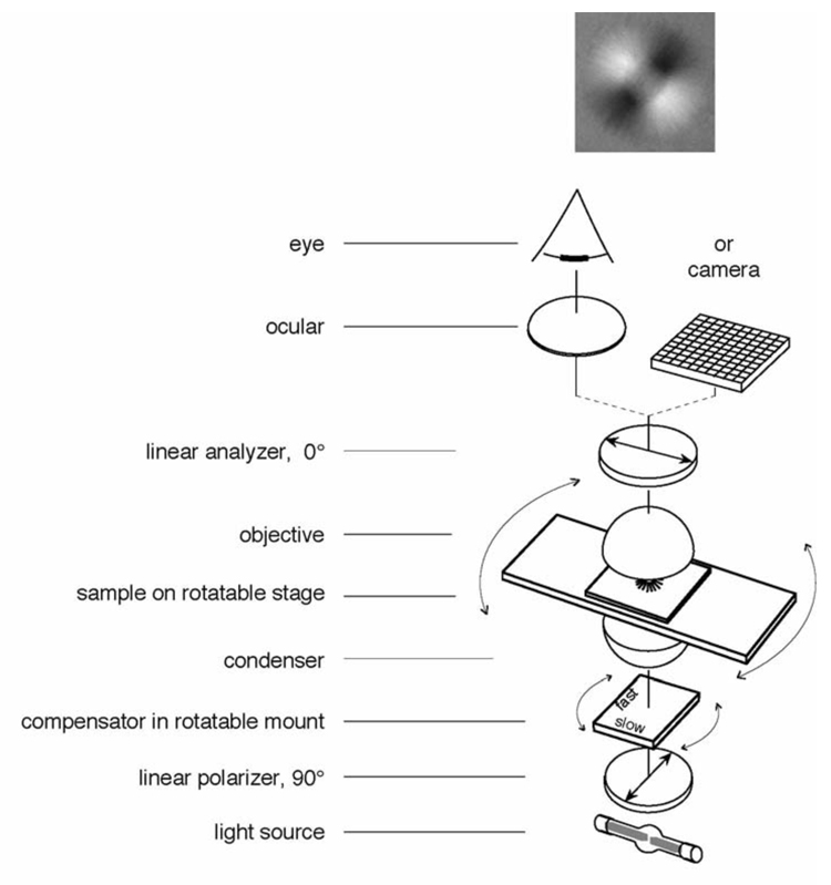
Figure 1.
Schematic of optical arrangement of the traditional polarized light microscope. The specimen image, as projected by the objective lens, is presented through an ocular to the eye and/or directly captured by a camera. The top image shows the appearance of an aster (a centrosome isolated from surf clam egg with radially arranged microtubules) between crossed polarizers and a Brace-Köhler compensator. The compensator is rotated slightly away from the extinction position in such a way that microtubule arrays that are oriented diagonally from top left to bottom right are bright because they run more parallel to the compensator slow axis. Microtubule arrays that are oriented diagonally from bottom left to top right are darker than the background because the MTs run more perpendicular to the compensator slow axis (see section 3.2).

