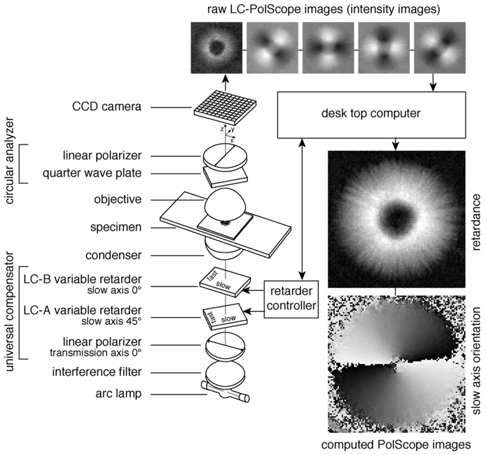
Figure 2.
Schematic of the LC-PolScope. The optical design (left) builds on the traditional polarized light microscope with the conventional compensator replaced by two variable retarders LC-A and LC-B forming the universal compensator. Images of the specimen (top row, aster isolated from surf clam egg) are captured at five predetermined retarder settings that cause the specimen to be illuminated with circularly polarized light (first, left-most image in top row) and with elliptically polarized light of different axis orientations (second to fifth images). The retardance and orientation images near the bottom right were both computed from the same five intensity images shown in the top row.

