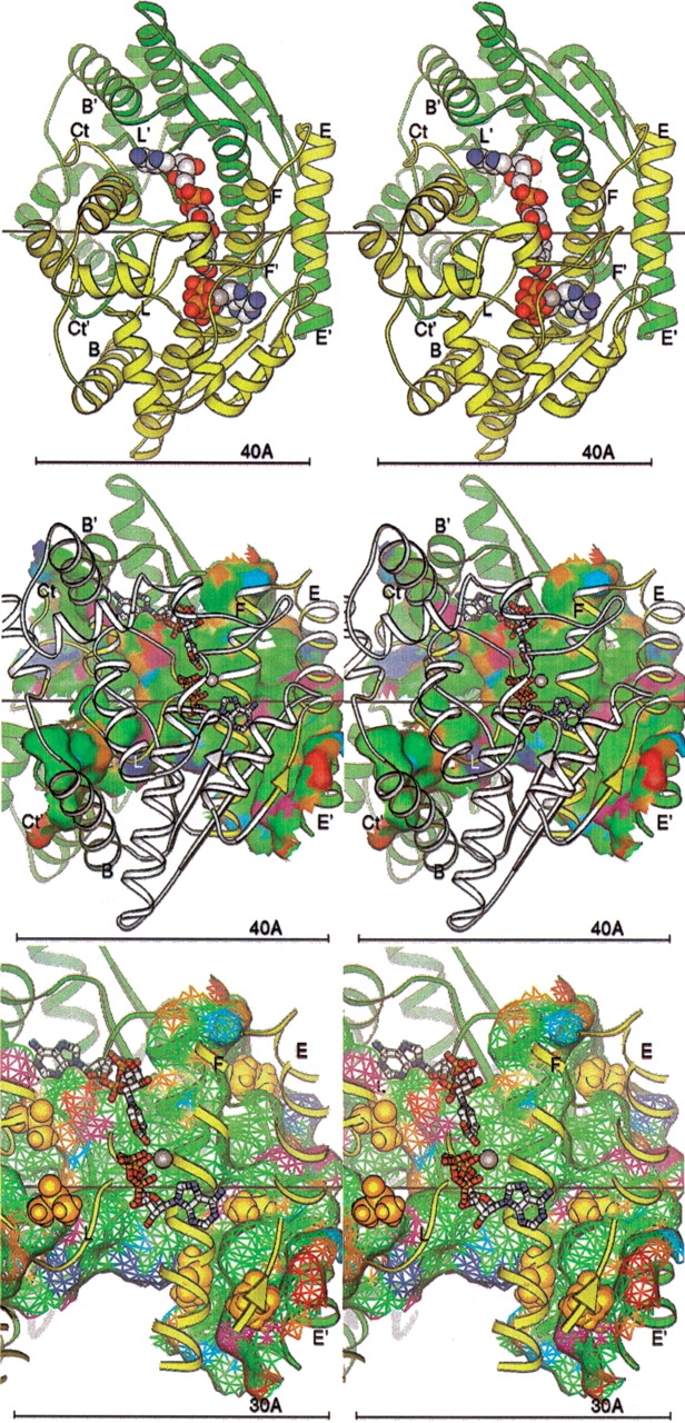
Figure 7.

(Top) NAD+ synthetase dimer. The A (yellow) and B (green) subunits are represented by ribbons. Key secondary structural elements are labeled; those of the B subunit are primed. The cofactors NaAD, ATP, and Mg+2 ion are shown as spheres. The twofold symmetry axis is shown as a black line, aligned with the X-axis of the page. All molecular figures created with Ribbons (Carson 1997; see also http://sgce.cbse.uab.edu/ribbons). (Middle) NAD+ synthetase dimer interface. The orientation is rotated about 45° about the Y-axis of the image above, to show the maximal amount of surface, and enlarged slightly. The cofactors are shown as ball-and-stick forms, and the A ribbons are drawn smaller to reduce clutter. Only the residues of the A subunit involved in the dimer interface are colored yellow; the rest are now white. Subunit B is green as before. The molecular surface of subunit B within 5 Å of any atom of subunit A is shown colored by atom type assigned for the docking experiments: positive charge, blue; negative charge, red; H-bond donor, cyan; H-bond acceptor, orange; polar, magenta; hydrophobic, green. (Bottom) DMSO docking at the NAD+ synthetase dimer interface. The orientation and style is that of the middle panel, but enlarged. Only the residues of the A subunit involved in the dimer interface (yellow) are shown in the ribbon. The surface is shown as a mesh. The DMSO molecules docked to the dimer in the computer simulation are shown as gold spheres.
