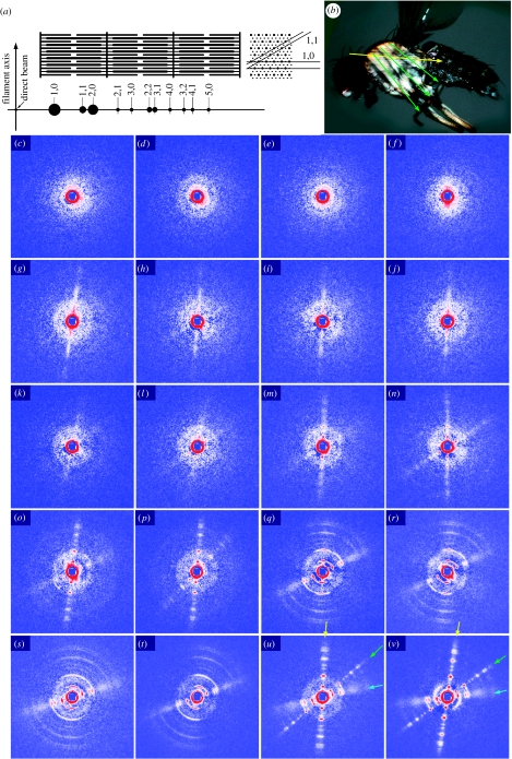
Figure 2.
Conventional X-ray diffraction recording from the thoraces of pupae at various developmental stages and of adult flies. (a) Schematic of the sarcomere structure in insect flight muscle and the equatorial reflections recorded from it. In the cross section, only the 1,0 and 1,1 lattice planes are indicated. (b) Muscle fibre orientations in flight musculature. Yellow arrow, DLM; green arrows, DVM. The equatorial reflections are generated in the direction perpendicular to these arrows. (c–v) Diffraction from pupae at various developmental stages and from adult flies. To describe the adult patterns first (u,v), they consist of three sets of equatorial reflections. The reflections indicated by the yellow and green arrows originate from the DLM and DVM, respectively. The near-horizontal set indicated by blue arrows is likely to originate from the tergotrochanter muscle. (c,d) Pupae at 16 h after puparium formation (APF) showing ring-like reflections with a spacing close to the 1,0 reflection. (e,f) Pupae at 26 h APF. (g,h) Pupae at 39 h APF showing a vertical streak of intensities corresponding to DLM. (i,j) Pupae at 51 h APF, (k,l) pupae at 61 h APF showing weak 1,0 peaks on the streaks. (m,n) Pupae at 74 h APF showing streaks for both DLM and DVM with weak peaks at 1,0 and 2,0 positions. (o,p) Pupae at 85 h APF, with stronger and sharper reflections, including those of higher orders. (o) The reflections from the tergotrochanter are observed for the first time (only 1,1 reflections). (q,r) Pupae at 98 h APF. (s,t) Pupae at 106 h APF (immediately before eclosion). Note that the reflections from the DLM and DVM are highly disoriented, while those from the tergotrochanter are not. (u) A freshly eclosed adult at 117 h APF. (v) An adult at 201 h APF. The patterns are after subtraction of isotropic diffuse scattering, due to various non-muscle components, by the method described by Iwamoto et al. (2003). The central blue square is due to the process of scattering subtraction. The gradation has been adjusted for each diffraction pattern for maximum visibility, so that the intensities of reflections in different panels should not be directly compared.

