
Figure 1. Schematic representation of the dichoptic viewing apparatus.
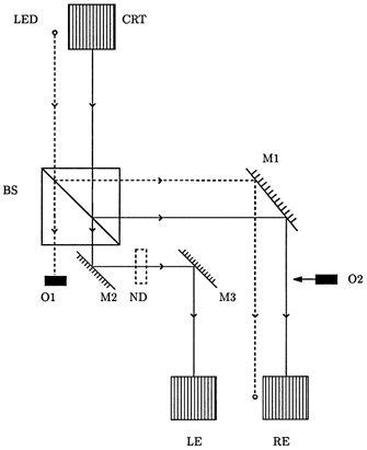
This shows the path from the cathode ray tube (CRT) display and light emitting diode (LED) to the left eye (LE) and right eye (RE) of the subject who is positioned at the lower margin of the figure, looking upwards. The beams are divided by the beamsplitter BS. The reflected beams are further reflected through 90 deg by the front silvered mirror M1. The right eye may thus view either both the LED and CRT or, after occlusion of the CRT beam by the movable occluder O2, the LED beam alone. Of the beams transmitted by the beamsplitter, the LED beam is occluded by the fixed occluder O1. The CRT beam is reflected twice through 90 deg by the front silvered mirrors M2 and M3. The two CRT beams are equalized by inclusion of the neutral density filter ND. Mirror M1 is mounted on a rotatable stage to allow adjustment of its orientation.