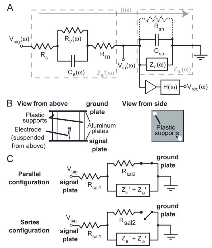
Figure 1.

Equivalent circuit model and methods. A: equivalent circuit model of a metal microelectrode in the brain adapted from Robinson 1968. The entire circuit is comprised of the electrode in the brain and the amplifier with a filter. The effective impedance of the electrode (Ze’) is comprised of the resistance of the electrolyte solution (Rs), the resistance and capacitance at the double layer interface of the electrolyte and the uninsulated electrode tip (Re and Ce) and the (negligible) resistance of the metal electrode (Rm). The effective input impedance of the amplifier (Za’) is comprised of the input impedance of the head-stage amplifier (Za) and the shunt resistance and capacitance to ground from the tip of the electrode to the input of the amplifier (Rsh and Csh). The triangle represents an ideal amplifier that draws no current. The non-ideal aspects of the amplifier have been accounted for in Za. Given the frequency-dependent potential at the electrode tip (Vsig(ω)), a current (I(w)) is drawn towards ground through the electrode and effective amplifier circuit, creating the potential (Vin(ω)) at the input of the amplifier which is subject to the frequency response of analog filters (H(w)) before being recorded (Vrec(ω)), all according to the equation: Vrec(ω) = H(ω)[(Vsig(ω)· Za’(ω))/(Ze’(ω) + Za’(ω))]. Thus, the microelectrode recording circuit corresponds to a voltage divider with a frequency-dependent gain due to the filtering of H(ω) and the frequency dependence of the impedances Ze’ and Za’. B: diagram of microelectrode testing apparatus. Two aluminum plates were connected and separated from each by non-conducting plastic supports, shown here from a top and side view. The apparatus was immersed in dilute saline with voltage signals applied to the signal plate with an electrode suspended from above 3 mm away. See the Methods section for more details. C: equivalent circuits for the parallel and series configuration. Rsal1 is the resistance for current to travel from the signal plate to the electrode tip in the saline, and Rsal2 is the remaining resistance for current to reach the ground plate.
