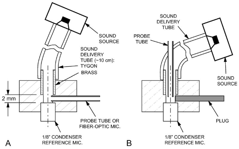
FIG. 3.

Section through the calibration coupler used (A) for microphone calibrations and (B) as an “artificial ear.” The sound delivery tube was 2.4-mm i.d. Tygon with a 2.4 mm i.d. ×6 mm long brass section that fit into the acrylic body of the calibration coupler (2.3 mm diameter in front of the -in. reference microphone). For the “artificial ear calibration,” the setup in (A) was used, the probe tube was replaced with a plug as in (B), and the brass tube was withdrawn about 3 mm from the position shown.
