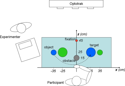
Fig. 1.
Experimental setup (top view). The participant is seated at the table, with the right hand resting at the starting position. Positions of objects (blue and green cylinder, 6 cm in height, 3 cm in diameter, with an enlarged stabilizing basis of 6 cm in diameter), target regions (blue and green disc, 10 cm in diameter, contralateral to the corresponding object), optional obstacle (cylinder, 15 cm in height, 6 cm in diameter), and the pre-trial fixation target (red ball 2 cm in diameter mounted on a frame at about eye height) are shown. The experimenter was seated at a separate desk facing the participant. The dashed line represents the object transport movement from object to target region in a “blue” trial. The x- and z-axis of the Optotrak system were approximately aligned to the axes indicated here, the y-axis was orthogonal to both (vertical axis)

