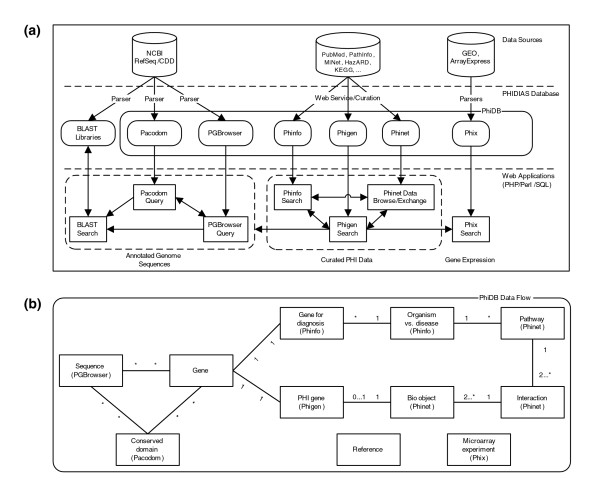
Figure 1.
PHIDIAS data flow. (a) The PHIDIAS system architecture. (b) PhiDB data flow among key elements of different PhiDB database modules. The relationships among these elements are represented by the following signs: *, zero or more; 1, one; and 2...*, two or more. For example, the labeling of a pathway with '1' and '2...*' indicates that one pathway includes two or more interactions.

