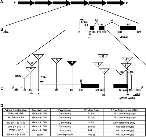
Figure 1.—
Mutator element insertion sites in P1-wr. (A) Illustration depicting the tandem repeats that make up the six-copy P1-wr complex. (B) Gene structure of one representative P1-wr copy in which exons (E) and introns (I) are shown. A bent arrow indicates the position of the transcription start site that is represented as +1. Positions of primers that were used for expression analysis of P1-wr-mum6 (see below) are represented by arrows. (C) Enlarged region of exon 1, intron 1, and the 5′ end of intron 2 showing the position of Mutator transposon insertions (triangles). Numbers inside the triangles correspond to the insertion lines (P1-wr-mum1–P1-wr-mum13) presented in Table 1. The solid triangle designates the gain-of-function mutation P1-wr-mum6. Primers that were used with genomic DNA to characterize the insertion lines are indicated as arrows. (D) Details of the PCR-based characterization of the P1-wr-mum6 allele. The amplification product size and the type of P1-wr copy amplified are listed for each experiment described in the text. P1-wr primers positioned 5′ and 3′ to the Mu1 insertion were used to amplify cDNA to determine the gene expression originating from wild-type copy (or copies).

