
Figure 5. Effects of dendritic sodium channel density (gNa) on the AP peak latency: computer simulation.
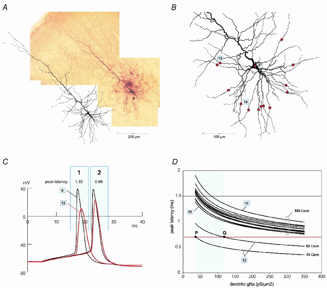
A, composite microphotograph of a biocytin-labelled layer V pyramidal cell in a 300 μm thick slice harvested from the rat somatosensory cortex (P27) aligned with a Neurolucida reconstruction of the same neuron. B, morphology of the pyramidal neuron after incorporation into NEURON (only basolateral dendritic arbor is shown). Red circles indicate recording sites on 13 basal dendrites. Each recording site is 150 μm from the centre of the soma. The somatic recording site is marked ‘0’. The dendrite with the slowest AP propagation velocity (largest peak latency) is marked ‘10’. The dendrite with the fastest AP propagation velocity is marked ‘13’. C, the model output in response to a square current pulse injection into the cell body. If Ri was set to 100 Ω cm the AP would propagate from the recording site ‘0’ to the recording site ‘13’ with 1.32 ms peak latency (sweep 1). If Ri was set to 43 Ω cm, the peak latency would match the experimental value of 0.68 ms (sweep 2). D, AP peak latencies at 13 recording sites marked by red circles in B are plotted versus dendritic gNa. The gK/gNa ratio was kept at 30/35 (Mainen & Sejnowski, 1996). All 13 curves in the upper part of the graph were generated in the model where Ri was set to 100 Ω cm. The curves generated by the slowest and fastest dendrite are marked ‘10’ and ‘13’, respectively. The horizontal red line marks 0.68 ms, the experimentally measured mean value of AP peak latency in basal dendrites 150 μm from the soma. Note that none of the 13 curves in the upper part of the graph cross the red line, thus models with unusually high densities of dendritic sodium channels (350 pS μm−2) cannot match experimental data if Ri was set to 100 Ω cm. In the lower part of the graph AP peak latencies obtained from the recording site ‘13’ are plotted versus dendritic gNa. In these two simulations Ri was set to 43 and 60 Ω cm in order to match the experimental data. The turquoise area represents the region of popular dendritic gNa values used by computational neuroscientists. The turquoise parameter range begins at 35 pS μm−2 (Mainen & Sejnowski, 1996) and ends at 120 pS μm−2 (Rhodes & Llinas, 2001). P and Q mark the interception of the model output (curves 43 and 60 Ω cm) and experimentally obtained peak latency (red horizontal line), inside the plausible range for dendritic gNa (turquoise area). Note that any model output curve between 43 and 60 Ω cm would intercept the red line inside the turquoise area (between P and Q).