
Figure 4. Alignments of the body and segments after tilting the support surface.
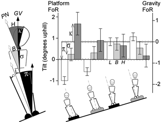
The alignment of the leg, body and head segments (L, B, H) is shown for each of the four freestanding conditions of stance and support indicated by the figures below. They are plotted in the platform frame of reference (FoR) on the left axis. They can also be read downward with the right axis (illustrated in the first group) to give the tilts in the opposite direction in the gravitational reference frame (κ, σ, π). The error bars on the Tilt and Vertical axes represent the S.E.M. associated with tilting the platform. Most obvious are the differences between the feet-apart and feet-together responses. Note the axis scale here spans just 3 deg whereas that of Fig. 3 spans 10 deg to illustrate the tandem stance data.