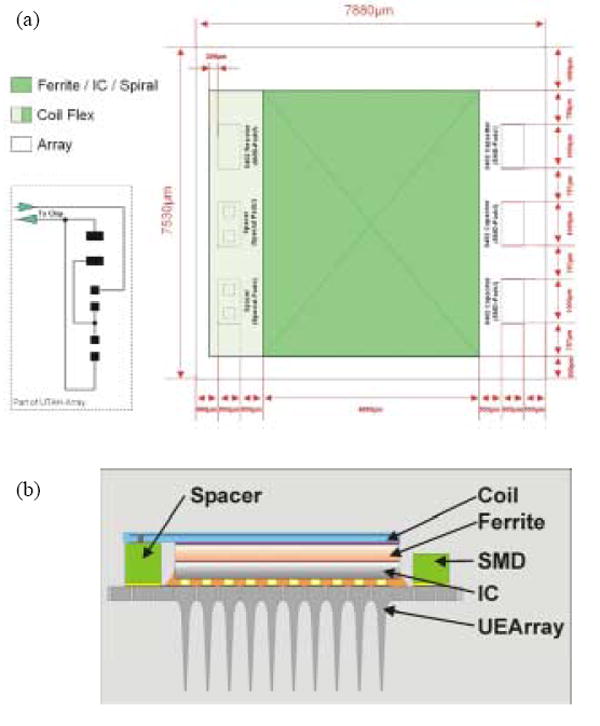
Fig. 4.

(a) Interconnection layout of the coil and other components. Two spacers and a jumper on the left side can be used for single or double coil assembly. The switchable interconnection plan is shown on the bottom left side. (b) Schematic of the cross sectional view of the integrated neural interface device.
