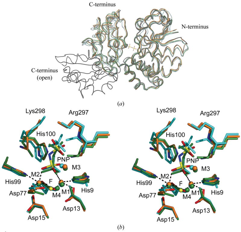
Figure 2.

(a) Superposition of the S. agalactiae PPase monomer on four previously solved family II PPase structures. On the right-hand side is the larger N-terminal domain; on the left, the smaller C-terminal domain. All structures are presented as loop models. The PNP ligand of S. agalactiae PPase is included to mark the active site. The S. agalactiae PPase is in orange, the S. mutans PPase (PDB code 1i74) is in cyan, the S. gordonii PPase (PDB code 1k20) is in black, the open-conformation B. subtilis PPase (PDB code 1k23) is in black and the PNP-complexed B. subtilis PPase (PDB code 2haw) is in green. The superpositions were calculated using O (Jones et al., 1991). (b) Stereoview of the superposition of the active sites of three family II PPases. The active-site residues and ligands are shown as sticks and the metal ions as spheres. The B. subtilis PNP complex (PDB code 2haw) is shown in green. S. mutans (PDB code 1i74) in complex with sulfates is shown in cyan. The S. agalactiae PPase is shown in orange, with N atoms in blue, O atoms in red and P atoms in yellow. The metal ions, shown as spheres, were coloured with the same colours as the superposed molecules. The F− ion in 2haw is shown as a yellow sphere for comparison. The coordination geometries at M1 and M2 in S. agalactiae PPase are marked with black dashes. The superpositions were made using O (Jones et al., 1991).
