
Figure 1.
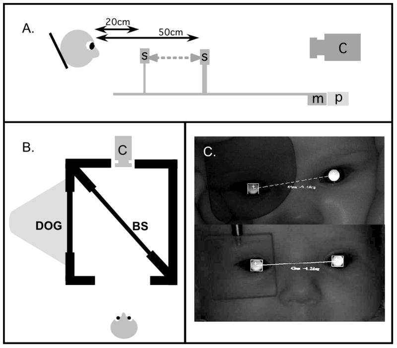
The experimental apparatus. Panel A: For the CL and VOL ramp protocols, the stimulus, S, was moved by a motor, m, along a track in front of the stabilized subject. The stimulus position was recorded using a linear potentiometer, p, and the responses were recorded using a photorefractor, c. Panel B: In the AOL protocol, the subject viewed a DOG target via a beamsplitter, while responses were recorded with the photorefractor. Panel C: An IR filter was placed before one of the subject’s eyes in the VOL condition. The photorefractor could collect data binocularly, as shown in the top image, although the subject could not see through the filter. A prism was placed before the eye for the AOL condition, as shown in the bottom image.