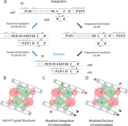
FIGURE 1.
λ site-specific recombination and models of arm-type Int binding in integrative and excisive recombination HJ intermediates. A, integration requires Int and IHF and proceeds via Int-catalyzed top-strand cleavages (small arrows) at core sites C and B followed by strand swapping at the left boundary of the 7-bp homologous overlap region (top strands in red, bottom strands in green) to form the integrative HJ intermediate. After isomerization, the HJ is resolved by bottom-strand cleavages at core sites C′ and B′ to generate the attR and attL of the integrated prophage. Excision requires Int, IHF, Xis, and FIS (when Xis is limiting) and proceeds with the same order of strand exchanges (top strands first) to regenerate attP and attB. Protein binding sites required for each reaction are highlighted in bold: Int arm-type sites (P1, P2, P′1, P′2, and P′3), Int core-type sites (C, B, C′, and B′), IHF binding sites (H1, H2, and H′), Xis binding sites (X1, X1.5, and X2), and FIS binding site (F). Structure-predicted, putative non-canonical Int binding sites (12) are marked NC with a dashed line over their predicted locations in attP and attR; half-arrows above the arm-type sites denote their relative polarity. B, C, and D are schematic depictions of tetrameric Int-HJ structure and the predicted arm-type site binding patterns in the modeled recombination intermediates (adapted from Biswas et al. (12)). B, in the x-ray crystal structure of the minimized, symmetrized tetrameric Int-HJ complex, four core-type Int sites (C, B, C′, and B′) comprising the four branches of the HJ (dotted lines) are bound by the Int core binding and catalytic domains (large orange and green circles), each of which is joined to its corresponding amino-terminal domain (small circles) by a linker region (small lines). The amino-terminal (N) Int domains are circularly displaced and bind to the indicated arm-type site, P′1, or P′2 encoded on two short oligonucleotides (gray bars). C, in the modeled integrative recombination intermediate, the P′1 and P′2 sites present in the crystal structure are replaced by arm-type sites P1, P′2, P′3, and a non-canonical site (NC, bold). D, in the modeled excisive recombination intermediate the P′1 and P′2 sites present in the crystal structure are replaced by arm-type sites P2, P′1, P′2, and a non-canonical site (NC, bold). In panels C and D, the solid heavy arrows denote where the arm-type site DNA would connect (in cis) to branches of the HJ (see depictions of HJ intermediates in panel A, above); red arrows depict connectivity between the P arm DNA and the HJ branch containing the C core-type site; black arrows depict connectivity between the P′ arm DNA and the HJ branch containing the C′ core-type site; the regions of DNA not depicted in these schematics encode the binding sites for the accessory proteins (see panel A above) that facilitate the formation of Int bridges between the arm- and core-type sites by bending the intervening DNA.

