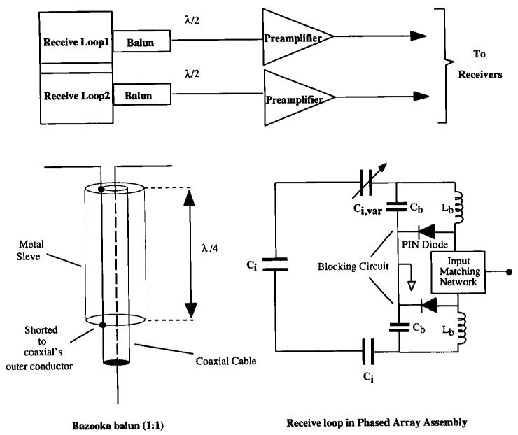
FIG. 3.
Schematic diagrams of the phased array assemblies and associated electronics. The coil resistance is 50 ± 10 Ω at resonance, with the sample present so no other matching network was employed. Cable resistances are 50 Ω. λ denotes tuned cable lengths in wavelength units at the 1H NMR resonant frequency, C denotes capacitance and L denotes inductance. Low input impedance pre-amplifiers were used.

