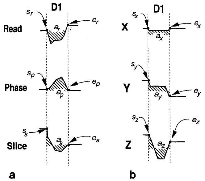
FIG. 2.

(a) The starting gradient values, s, the ending gradient values, e, and the areas, a, for slice, readout, and phase encoding directions. The subscripts r, p, and s represent the readout, phase encoding, and slice directions, respectively. The waveform shapes in D1 (the dead-period 1) are arbitrary. (b) The starting and ending gradient values and the areas for amplifier current directions. These parameters are calculated using Eq. [l]. The subscripts x, y, and z represent the amplifier directions. Trapezoidal waveforms with maximum slew rates are designed using the three parameters in each direction.
