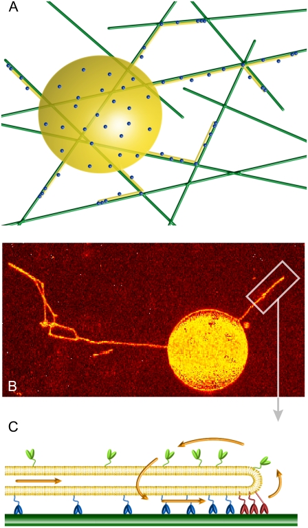
FIGURE 1.
System geometry. (A) Sketch of the experimental setup. A giant unilamellar vesicle (yellow), partially covered with kinesin-1 motors (dots), is placed over a network of microtubules (green) in presence of ATP. The motors bound to microtubules apply forces on the membrane and pull membrane tubes (yellow). (B) Confocal image of membrane tubes pulled by kinesin motors from a giant unilamellar vesicle. The image is a two-dimensional projection of the three-dimensional confocal reconstruction. The membrane was uniformly labeled with fluorescent lipids (TRITC-DHPE). The image is shown in false color to enhance contrast. Bar, 5 μm. (C) Sketch of the treadmilling mechanism for membrane tube extraction (in the membrane tube reference frame), where the motor fluxes are represented by arrows. The bound motors at the tip (red) move against the tube force F with velocity V and detach from the microtubule (dark green) at a rate ku. The bound motors along the tube (blue) do not support any substantial force, move with velocity V0 (motor velocity under vanishing load), and detach from the microtubule at a rate  The motors not bound to the microtubule (unbound motors; light green) attach to the microtubule at a rate kb. These unbound motors diffuse along the membrane tube (yellow) and are dragged by the membrane tube itself as it grows.

