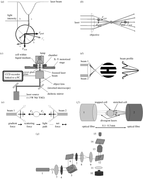
Figure 1.
Working principles of optical tweezers. (a) The scattering (Fscat) and gradient (Fgrad) components of optical forces on a dielectric sphere due to a Gaussian laser beam (light intensity increases from b to a). (b) Schematic of optical tweezers. Light enters the objective lens of a microscope and is focused to a diffraction-limited beam waist, creating a three-dimensional light gradient; a particle that is out of trap is brought back to the centre of the trap. (c) Typical experimental set-up of optical tweezers, adapted from the technical note of Cell Robotic Inc., USA. (d) Two-beam interferometric optical tweezers, adapted from Chiou et al. (1997). (e) Schematic of gradient and scattering forces for two beams, adapted from Constable et al. (1993). (f) Schematic of optical stretcher, adapted from Guck et al. (2000). (g) Schematic of holographic optical tweezers generated from a spatial light modulator (SLM), adapted from Martin-Badosa et al. (2007). 1, laser beam; 2, LC lens; 3, LE lens; 4, polarizing element; 5, SLM; 6, dichroic mirror; 7, polarizing element; 8, telescope; 9, telescope; 10, CCD camera; 11, tube lens; 12, dichroic mirror; 13, microscopic objective; 14, sample; 15, illumination.

