
Figure 8.
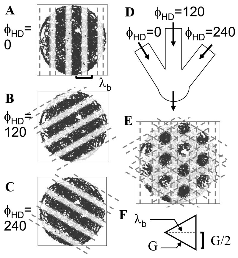
Combination of bands of interference from different dendrites results in the grid cell firing pattern. Each head direction cell causes interference with consistent spatial wavelength in bands running perpendicular to the selective direction preference of the individual head direction cell. A–C. Interference bands due to modulation of dendritic frequency by head direction cells with specific direction preferences angles at zero (A), 120 degrees (B) and 240 degrees (C). D. Schematic of the interaction of different dendrites with interference bands modulated by input from different head direction cells. E. The product of interference bands due to different dendritic oscillations cause the soma to cross firing threshold in a pattern matching grid cell firing fields. F. Equilateral triangle illustrating the relationship between the spatial wavelength λb of band interference (height of triangle) and the grid cell spacing G (length of one side).