
Fig. 6.
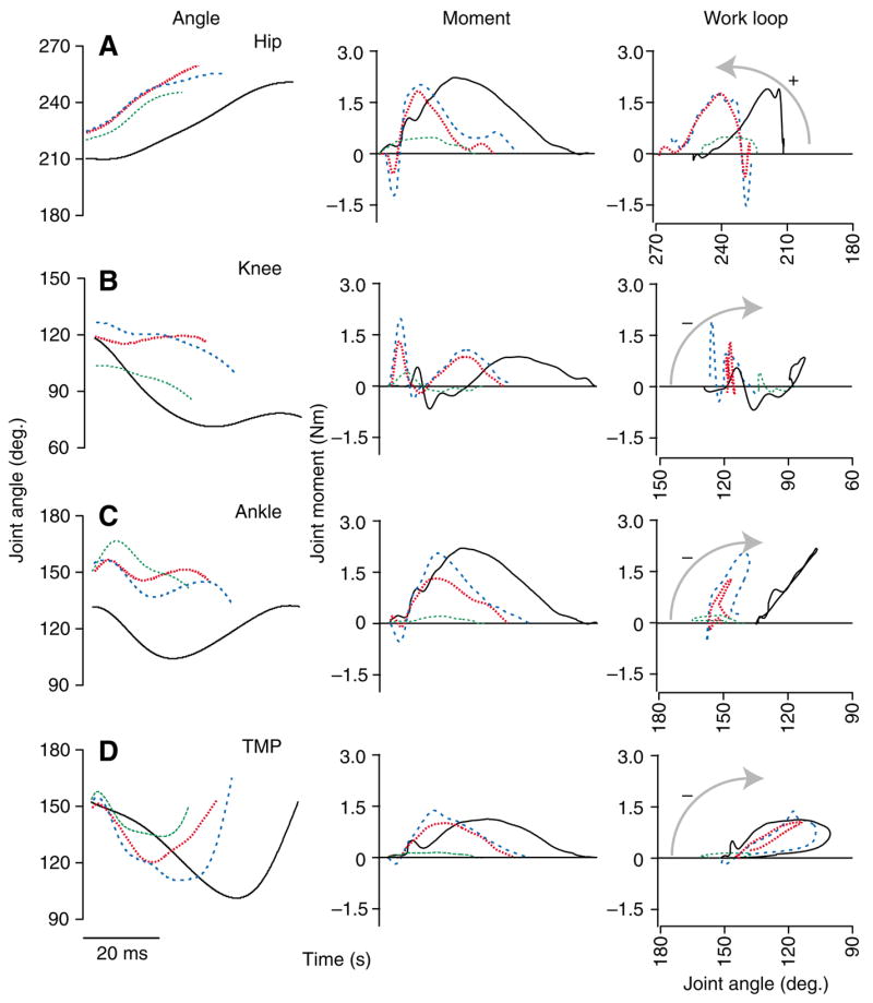
Joint mechanics during stance. Joint angles (left), external moments (middle) and joint work loops (moment–angle plots, right) over the course of stance for the hip (A), knee (B), ankle (C) and TMP (D). A representative U trial for each of the 3 response modes is shown (broken colored lines) with a level running trial for comparison (C, solid black line). Increasing joint angles indicate extension, and positive moments indicate extensor moments. Arrows indicate the direction of work loops. Counter-clockwise indicates energy production by the joint, clockwise indicates energy absorption.