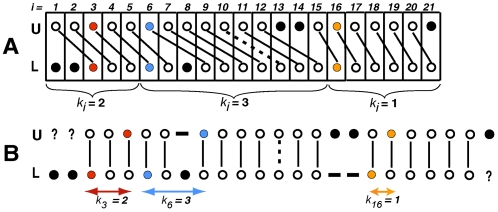
Figure 3. Two renderings of the same alignment, illustrating the concept of phase shift.
Circles represent bases and links represent positional homologies: solid links–matches, and dashed links–mismatches. Black closed circles represent bases that have no positional homologs. In (A) vertical columns represent successive configurations of an aligned solution. The pairs of bases at sites 3, 6, and 16 are colored. Curly brackets mark segments aligned with different phase shifts. In (B) vertical columns contain pairs of positional homologs, and gaps are inserted opposite to bases having no homologs; external gaps are shown as question marks. The horizontal distances between the bases of each colored configuration (arrows) represent the corresponding phase shifts ki.

