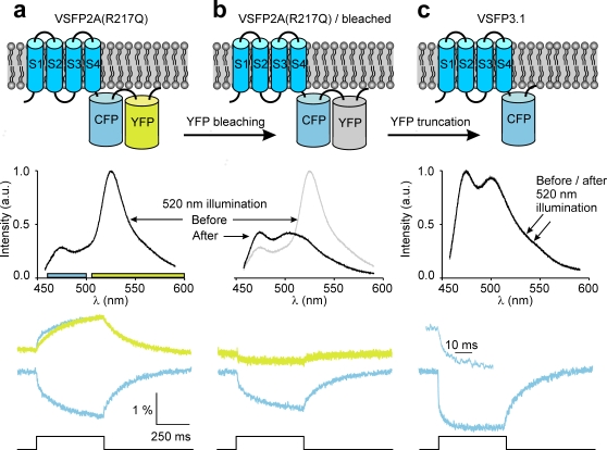
Figure 2. Development of a fast reporting VSFP.
The membrane topology of VSFP2A(R217Q) (a), VSFP2A(R217Q) after photobleaching YFP (b) and VSFP3.1 (c) are shown in the top panel. Underneath are emission spectra recorded from each construct using 440 nm excitation light. The lower panel shows the fluorescence signals recorded in the yellow and cyan channels. For VSFP2A(R217Q) a scaled mirror-image of the cyan signal is shown aligned with the yellow signal; note the fast CFP component. For VSFP3.1 the onset of the fluorescence signal is shown on an expanded time scale; note the dramatically faster response of VSFP3.1.

