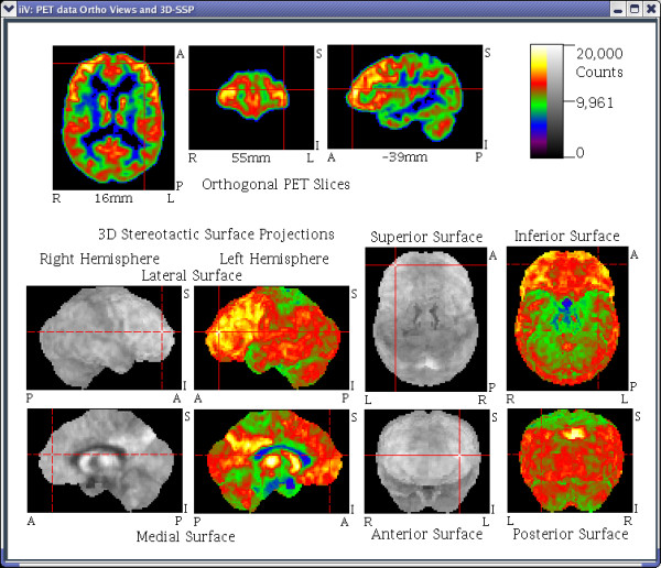
Figure 9.

The top 3 images show orthogonal views of raw PET data. The bottom 8 images show the same data converted to 3D stereotactic surface projections by NEUROSTAT software [20]. The surfaces are shown with both gray and pseudo color tables to highlight the influence of color on contrast. Solid crosshairs indicate an image is showing the currently selected voxel, where as dashed crosshairs indicate the currently selected voxel is not visible in the image but is located somewhere orthogonal to the crosshairs. Notice the left hemisphere lateral surface, the superior surface, the anterior surface and the orthogonal slices are all showing the currently selected voxel while the other surface views are not.
