
Figure 2.
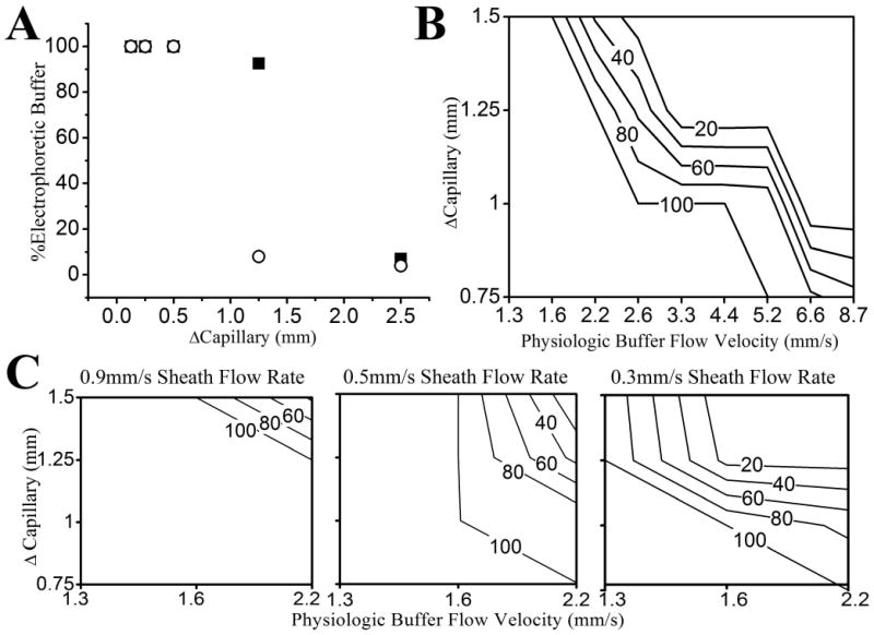
Optimization of the flow rates and dimensions for the coaxial CE system A) Shown is the percentage electrophoretic buffer entering the capillary as a function of Δcapillary for two different-diameter coaxial tubes, 1.2 mm (solid squares) 0.9 mm (open circles). Other system parameters were a sheath flow rate (0.17 ml/min), physiologic buffer rate (5.5 ml/min), and a square chamber geometry. B) The percentage electrophoretic buffer entering the capillary was plotted as a function of the velocity of the physiologic buffer and Δcapillary for a constant coaxial sheath flow velocity of 0.9 mm/s in the rectangular chamber. The topographical lines represent the percentage electrophoretic buffer entering the capillary. C) The percentage electrophoretic buffer entering the capillary was plotted as a function of physiologic buffer velocity and Δcapillary for various coaxial sheath flow velocities (0.3-0.9 mm/s) in the rectangular chamber. The topographical lines are the percentage electrophoretic buffer in the capillary.