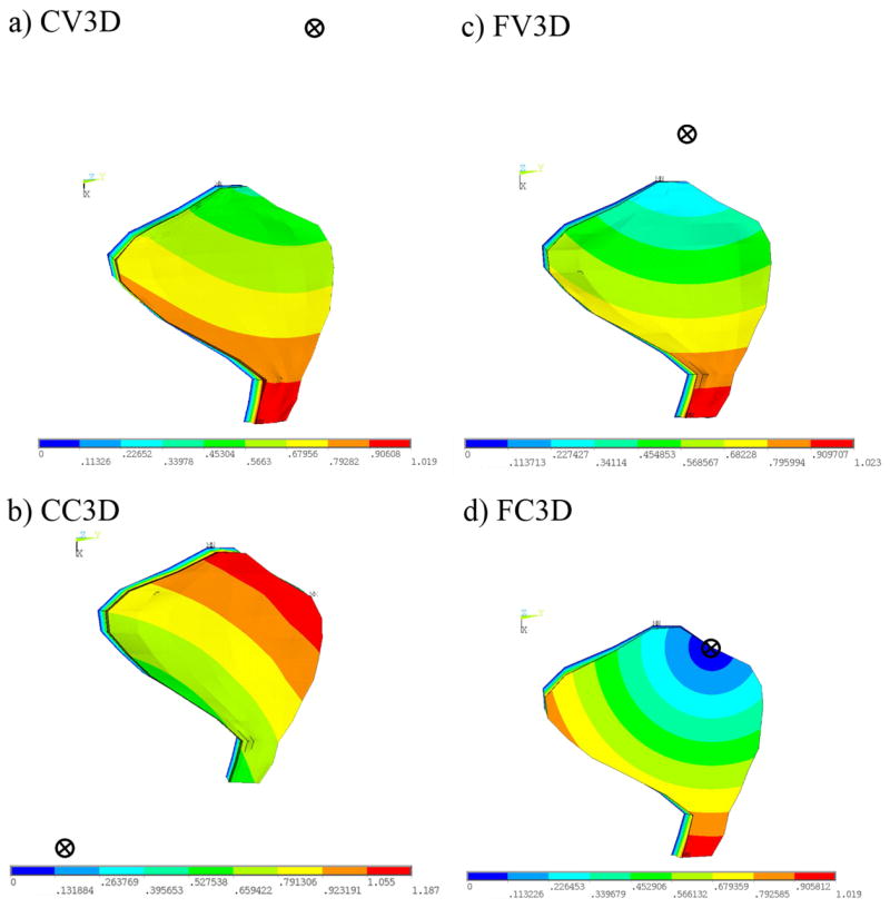
Fig. 9.

Mode shapes and centers of rotations corresponding to first natural frequency of 3D OM models. This figure indicates the displacement magnitude (red = large, blue = small) and the center of rotation (circle with an X) for each of the mode shapes corresponding to the 1st natural frequency for each of the 3D OM models. The deflection in the first mode causes a shearing of the CFL. This shearing, however, is no longer restricted to be parallel (or perpendicular) to the LM transect, as is the case in the 2D OM models. The center of rotation is located by calculating the intersection of two lines drawn in the macular plane and perpendicular to the directions of deflection of two points in the OL.
