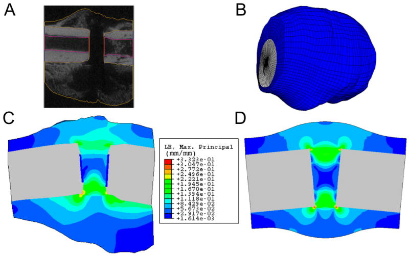
Fig. 1.

Creation of a finite element model of a rat fracture callus from micro-computed tomography (μCT) image data. A: Semiautomated image segmentation is performed to define the boundaries of the cortex and callus in each image. B: The resulting finite element mesh. C: An estimate of the distribution of maximum principal strain on a longitudinal section of the callus using the finite element mesh shown in Fig. 1, B. Displacements were applied to the left end of the cortical bone to create an 11° bending angle. D: An estimate of the distribution of maximum principal strain on a longitudinal section of a callus of idealized geometry. Displacements were applied in the same manner as in Fig. 1, C. In addition, the μCT-derived and idealized geometry meshes have identical gap size, cortical thickness, and medullary canal diameter, as well as comparable maximum callus diameters. The same tissue material properties and comparable element sizes were used in both analyses. Results are only shown in the callus tissues and not in the cortex or medullary canal.
