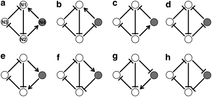
FIGURE 1.
Eight possible configurations of the repressilator with an additional regulator forming a coupled feedback structure. Open circles represent the elements of the original three-node repressilator and the solid circle denotes the additional element newly introduced. The arrow denotes activation and the blunted line indicates repression. Nodes are labeled from N1 to N4, as shown in panel a.

