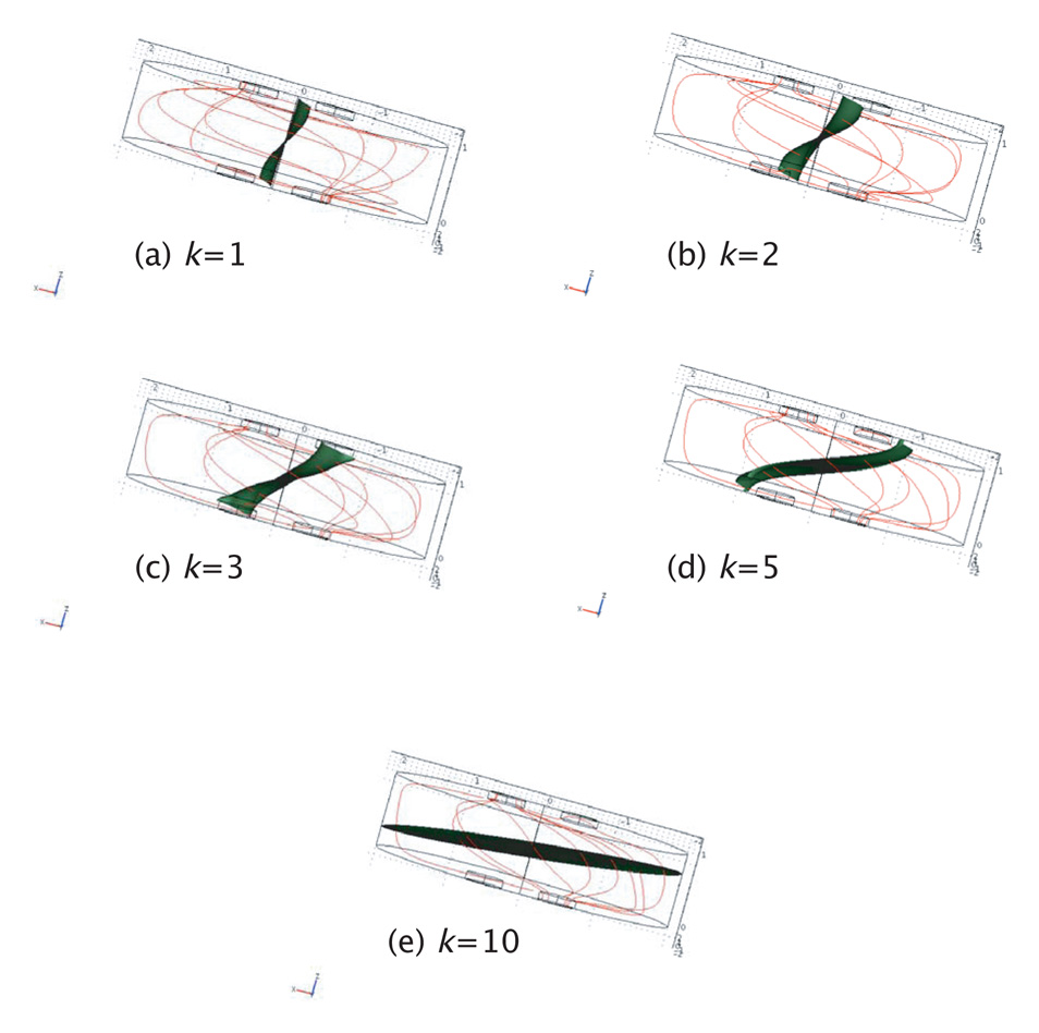
Figure 5.
Current streamlines (red) and zero-volt isosurface (green) plotted for the case h = a for anisotropy ratios of (a) 1 (isotropy), (b) 2, (c) 3 (d) 5 and (e) 10, showing a minimum in differential voltage (isosurface crossing through voltage electrodes) at around k=2. The finite element model used in these calculations had 599 495 degrees of freedom and 432 680 linear tetrahedral elements.

