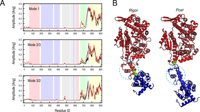
Figure 6. Rigor-like and post-rigor lowest-frequency modes that are essentially independent of the motor head.
(A) Amplitude of the Cα fluctuations along the sequence computed upon optimal superposition of the head domain (aa 61–699) for the three lowest-frequency modes. Black and red profiles correspond to the rigor-like and post-rigor states, respectively. In the background, pink, light blue, grey, light green, cyan, and yellow indicate the boundaries of the N, U50, L50, C, IQ, and ELC subdomains. Rigor-like and post-rigor fluctuations show a difference in the conformational freedom of the converter in the two states (light green region). (B) DynDom analysis of the rigor-like and post-rigor lowest-frequency modes. In both cases two dynamic domains corresponding to the head domain (red) and the neck region (blue) are identified. The analysis indicates that the converter subdomain (shown surrounded by a dashed circle) belongs to the head domain in the rigor-like state and to the neck region in the post-rigor state.

