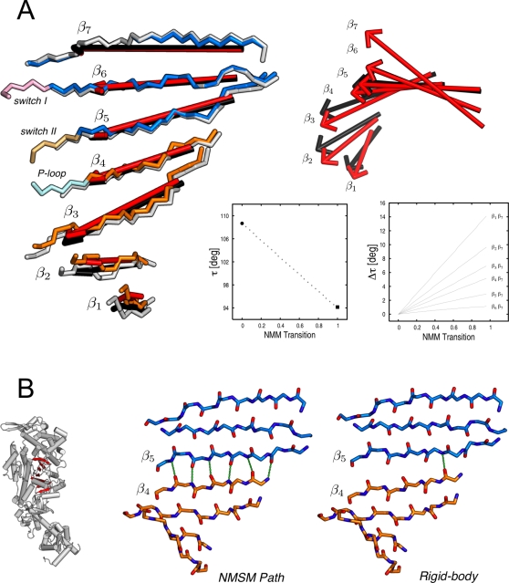
Figure 11. Structural rearrangement of the 7-stranded β-sheet.
(A) Side and top views of the central β-sheet are shown on the left- and right-hand side of the panel, respectively. Individual β-strands, βi, are represented by red and black arrows indicating the direction of the rigor-like and NMSM post-rigor β-strand vectors, respectively. In the box diagrams, the twist of the entire sheet, τ, and the difference in the twist angle between the individual strands and β7, Δτi
,7, relative to the rigor-like conformation are monitored along the NMSM path. The former is computed as  , where
  and
and  are the unit vectors corresponding to the structural borders of the β-sheet; the latter as Δτi
,7(ξ) = ∥τi
,7(ξ)−τi
,7(0)∥, where ξ = 0 indicates the rigor-like conformation and ξ = 1 the NMSM post-rigor conformation. (B) The comparison of the NMSM post-rigor conformation with the structure obtained by the pure rigid-body motion described by the screw axes given in Table 3; see text. The inset on the left shows the structural location of the central β-sheet in the myosin head.

