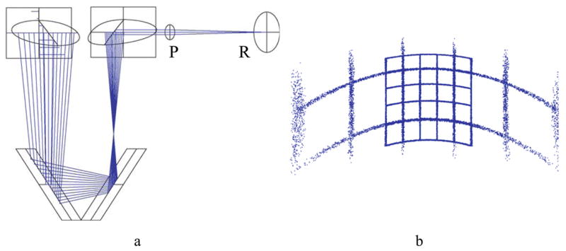
Figure 14.

a) 3D layout and ray tracing of the off-axis parabolic mirror design showing eye pupil (P) and retina (R). . Rectangles represent effective areas for the first and second surfaces of the carrier lens. b) Image from two square 5×5 grid objects, subtending 5° and 15° respectively. Notice the similarity of the distortion to that shown in Fig. 9.
