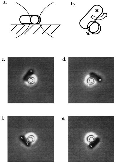
Figure 1.
(a) A tethered cell stalled by a bead held in the trap, viewed from the side. (b) The same cell viewed from below the coverslip. The large arrow represents the torque exerted on the cell body by the flagellar motor; the small arrow represents the resulting displacement of the bead away from the center of the trap. The initial position of the bead is shown by the gray circle. (c–f) Video-recorded images of a tethered cell pushing a trapped bead as the tether point was rotated clockwise at −1/8 Hz, driving the motor backwards. In each panel, the black circle and the white cursor are fixed relative to the center of the trap, allowing the displacement of the bead to be seen. The cross (x) marks the approximate position of the tether point. The first panel shows the same view as the diagram in b.

