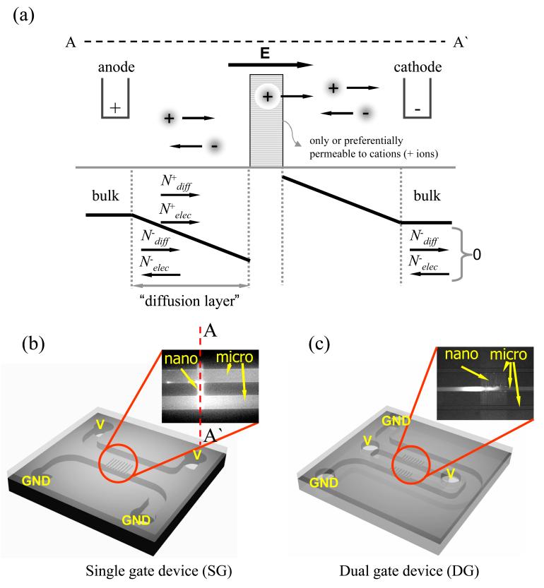
Figure 1.
(color online). (a) Schematic diagram of ion concentration distribution front and back of perm-selective material which only let cations pass through. Ions in anodic side were depleted while they were enriched in cathodic side. Schematic configurations of (b) single gate device (SG) and (c) dual gate device (DG). GND is electrical ground.

