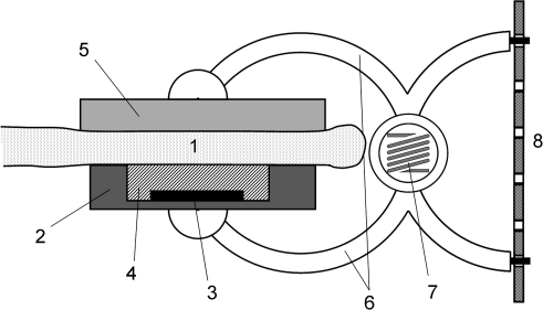
Fig. 1.
Schematic diagram of the leaf patch clamp pressure probe. A leaf patch (1) was clamped between two planar circular pads. One pad (2) was made of steel (diameter=6 mm; height=1.5 mm) and contained a receptacle (area=4×2.5 mm2; height=0.8–1.2 mm) for integration of the sensor chip (3) which is covered with a thin silicone membrane (4). The pressure-sensitive area of the chip used was either 1.3×1.3 mm2 or 1.9×1.2 mm2. The counter pad (5) was made of aluminium (diameter=8 mm; height=1 mm). The pads were attached to two curved arms (6) bridged by a spring (7) in the middle (Wolfcraft GmbH; microfix S, B3630Fz60; Kempenich, Germany). The clip was made of synthetic material. Optimum adjustment of the clamp pressure, Pclamp, to leaf thickness and stiffness was accomplished by a stiff strap (8), made of neoprene (rubber type CR-50, 50° Shore), containing regularly punched holes spanned between the arms of the spring clip at the handhold site.

