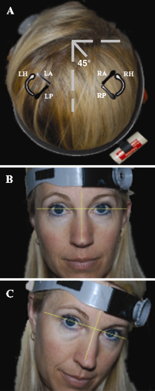
Fig. 1.
Rate sensor and headband fit for htDVA test of left anterior and right posterior semicircular canal function. (A) The headband was placed 45° relative to the midsagittal plane. The axis of maximum sensitivity of the rate sensor is aligned midway between the axes of the right posterior semicircular canal (RP) and left anterior semicircular canal (LA), which is approximately parallel. Each semicircular canal was tested independently, in its plane of excitation. The partially shaded semicircular canals illustrate the LARP plane. The black semicircular canals illustrate the right anterior (RA)/superior and left posterior (LP) canal plane (RALP). The right and left horizontal semicircular canals (RH, LH) are colored white. (B) Initial head position. (C) Final head position after the manually imposed head thrust.

