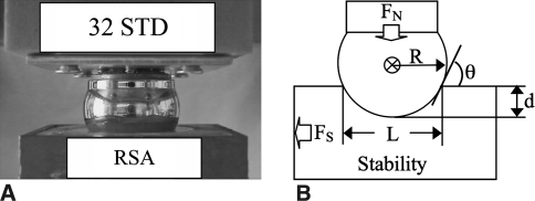
Fig. 1A–B.
(A) A photograph shows how the glenosphere (32 mm) lays on top of the standard humerosocket liner. (B) The diagram illustrates the stability model and its variables. FN = compressive force applied to glenosphere; FS = force required to dislocate glenosphere; R = radius of glenosphere; d = depth of humerosocket; L = chord length of humerosocket; θ = incident angle between the glenosphere and the humerosocket edge.

