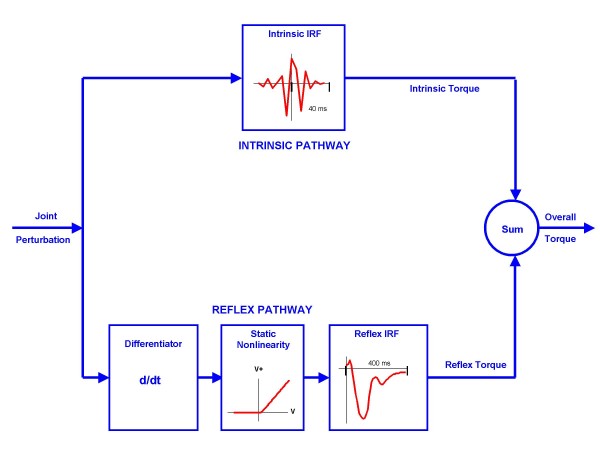
Figure 2.
Parallel Cascade System Identification Model. The parallel cascade structure used to identify intrinsic and reflex stiffness. Intrinsic dynamic stiffness is represented in the upper pathway by the intrinsic stiffness impulse response function. Reflex dynamic stiffness is represented by the lower pathway as a differentiator, followed by a static nonlinear element and then a linear impulse response function. The nonlinear element is a half wave rectifier which shows the direction of stretch. Filled areas show reflex torque. V represents perturbation velocity. V+ represents half wave rectified velocity.

