Fig. 1.
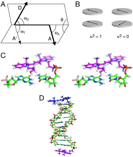
Orientation of transition moments of cyanine fluorophores terminally attached to double-stranded DNA. (A) The orientation parameter κ2. The transition dipole vectors for the coupled donor and acceptor fluorophores are indicated by the arrows, labeled D and A. Vector A′ is generated by the in-plane translation of vector A to share its origin with vector D. The definition of κ2, given in Eq. 4, is based on the angles shown. (B) If the fluorophores lie in parallel planes, the orientation parameter simplifies to κ2 = cos2θT and varies between 0 and 1. The schematic shows the limiting cases, where the transition moments are parallel (κ2 = 1) and crossed (κ2 = 0). Note that these conditions will occur twice per complete rotation of one fluorophore relative to the other around their common axis. (C) Parallel-eye stereoimage showing the structure of Cy3 stacked onto the terminal base pair of a DNA duplex, as determined by NMR (11). (D) A molecular graphics model of a duplex with Cy3 and Cy5 fluorophores attached to the 5′ termini via C3 linkers. This was generated by using our NMR structures of Cy3 and Cy5 attached to duplex DNA. Note that the fluorophores lie in approximately parallel planes, and that the angular relationship between them (and thus their transition moments) will depend on the length of the DNA helix and its helical periodicity.

