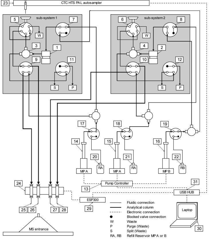
Figure 1.
Schematic of the 4-column, 2-mixer LC system. The components of subsystems 1 and 2 are: (1,2) mixers, (3,4) ‘tee’ flow split points, (5,6) injection valves, (7,8) mobile phase solvent selection valves, (9,10) column selection valves, (11,12) mixer purge valves. Other components include: (13) syringe pump controller, (14) mobile phase A syringe pump for subsystem 1, (15) mobile phase A syringe pump for subsystem 2 (16) mobile phase B syringe pump for both subsystems, (17) control valve for sub-system 1 pump A, (18) control valve for sub-system 2 pump A, (19) control valve for pump B, (20) refill reservoir for sub-system 1 pump A, (21) refill reservoir for sub-system 2 pump A, (22) refill reservoir for pump B, (23) autosampler that uses a single syringe, (24) encoding translation stages for positioning ESI emitters, (25-28) ESI emitters, (29) motion controller for encoding translation stages (30) laptop computer (31) USB HUB. For simplification, several components have not been shown, including electronic connections between the valves and the USB HUB, an on-line degasser and a 3-drawer cool-stack sample holder accessed by the autosampler. The valves of sub-system 1 are shown in positions for sample loading onto the column connected to emitter 26 and the valves of sub-system 2 are shown in positions for a gradient elution on the column connected to emitter 28. The direction of flow through each connection is illustrated. In the configuration shown there is no flow through the sample loop of sub-system 2 nor through any of the refill reservoirs.

