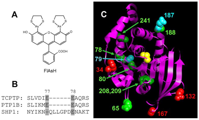
Figure 1.

(A) Chemical structure of FlAsH. (B) Representative example of the strategy used to choose TetraCys-insertion sites in TCPTP: the SHP1 PTP domain contains a natural insertion between residues 77 and 78 that is not present in most other PTPs, suggesting the potential tolerance of this region for non-natural insertions. (C) Positions of TetraCys insertions modeled on to the TCPTP crystal structure (Residues 5-277; PDB code: 1L8K).10 The TCPTP catalytic domain is shown as a ribbon, with amino acids that correspond to the sites of insertions shown in space-filling representation and colored as follows: red for insertions that rendered TCPTP unstable or inactive; green for insertions associated with modest FlAsH sensitivity; and cyan for insertions that gave rise to strongly FlAsH-sensitive TCPTP activity. The position of the C-terminal insertion is not shown, as TCPTP’s C-terminal portion is not present in the only solved TCPTP structure.10 For perspective, TCPTP’s active-site catalytic cysteine (Cys216) is shown in yellow.
