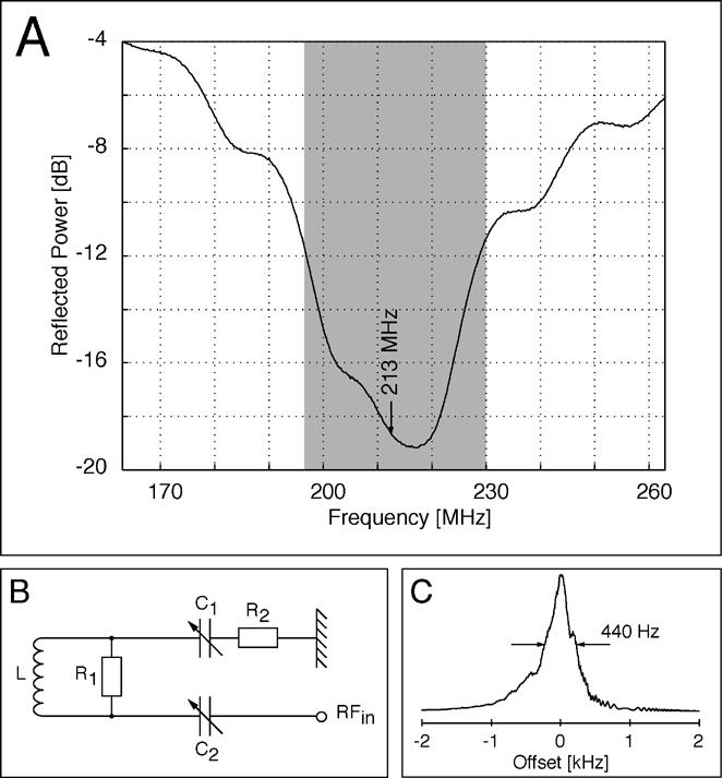
Figure 2.

Design of the field lock probe. A) Reflected power of the tuned probe over a range of 110 MHz. B) Circuit design of the lock probe consisting of a rf-coil L (7 turns, copper, AWG 16), resistor R1 (1.8 kΩ) in parallel with the rf-coil, resistor R2 (50 Ω) and two variable capacitors C1 and C2 (each 2-8 pF). C). Proton signal of the water sample.
