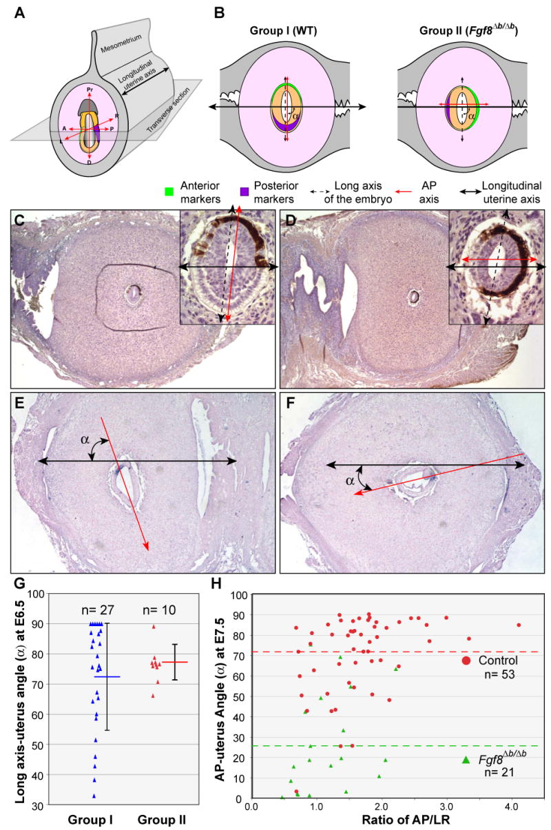
Figure 7.

Loss of Fgf8b alters the orientation of AP axis, but not the long axis of the embryo, with respect to the longitudinal axis of the uterine horn. (A) Schema of orientation of the embryo within the uterus and the relative position of the sectioning plane. (B) Schematic representation of relationships between the axes of the embryo and uterus found in two groups (I and II) of embryos at E6.5 from intercrosses of Fgf8+/Δb parents. (C and D) Immunohistochemistrical analysis of EGFP, which marks the AVE (brown labeling) on transverse sections of E6.5 embryos within the uterus. Insets show embryos at higher magnification. (E-F) In situ hybridization of T transcripts on cross sections of WT and Fgf8Δb/Δb embryos at E7.5 within the uterus. Red arrow represents AP axis, black double arrow marks the long uterine axis. Note the abnormal bulge of cells (arrowhead) at the primitive steak of Fgf8Δb/Δb embryos in F. (G) Distribution of the angles (α) between the long axes of the embryo and the uterus at E6.5 for groups II and I. Each dot represents one embryo. The average angles (horizontal bar) and standard deviations (vertical bars) are indicated. (H) Distribution of the angles (α) between the AP axes and the uterus at E7.5 for control and Fgf8Δb/Δb embryos relating to the ration of AP/LR dimension. The green and red dashed lines indicate the average angle for control and Fgf8Δb/Δb embryos, respectively.
