
Figure 2.
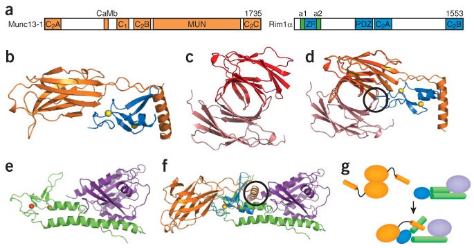
Munc13s and RIMs. (a) Domain diagram of Munc13-1 and RIM1α. The number of residues of each protein is indicated above each diagram on the right. The helices adjacent to the RIM1α ZF domain, which are involved in Rab3 binding, are labeled a1 and a2. The same color-coding is used in b,d–g. (b) Structure of the complex between the RIM2α ZF domain and the N-terminal region of Munc13-1, including the C2A domain60. Yellow spheres, zinc ions. (c,d) Structure of the Munc13-1 C2A domain homodimer60 (c) and superposition with the Munc13-1/RIM2α heterodimer (d). The two protomers of the Munc13-1 C2A domain homodimer are shown in red and salmon to distinguish them from the Munc13-1 C2A domain in the heterodimer. (e) Structure of Rab3A (purple) bound to the rabphilin N-terminal region containing its ZF domain and the two adjacent helices involved in Rab3 binding (green)78. Red spheres, zinc ions. (f) Superposition of the Munc13-1–RIM2α and Rab3A–rabphilin structures shown in b and e using the two ZF domains for the superposition. Black circles, regions of overlap between the RIM2α ZF domain and one Munc13-1 C2A domain protomer of the homodimer in d, and between Rab3A and the Munc13-1 α-helix at the C terminus of the C2A domain in f. (g) Model summarizing the structural rearrangements and changes in protein-protein interfaces proposed to occur during the switch from the Munc13-1 homodimer to the Munc13-1–RIM-Rab3 tripartite complex.