
Figure 5.
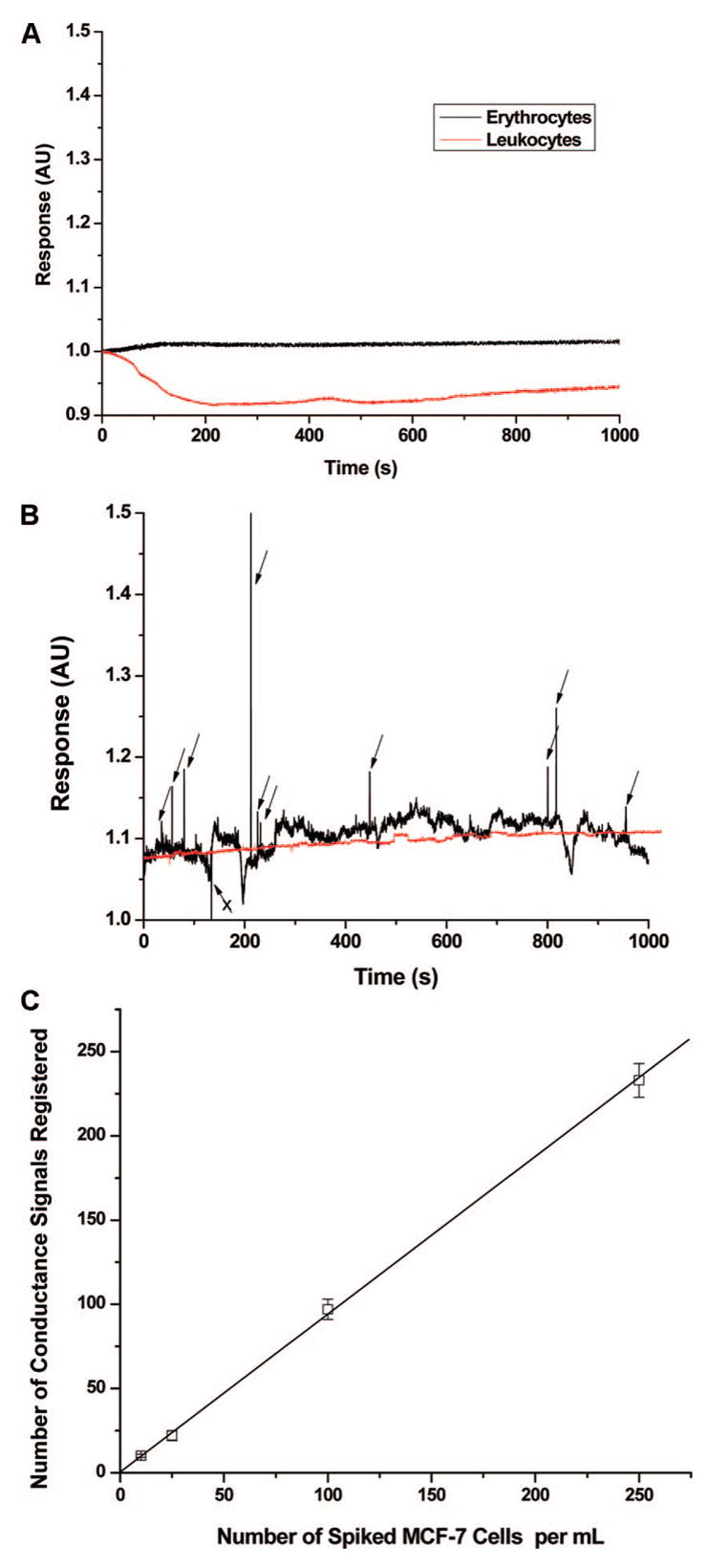
Conductance responses (in arbitrary units, AU) and calibration plots for CTCs are shown. (A) Conductometric response for suspensions of leukocytes and erythrocytes (cell density = 150 cells/μL) in TRIS-Glycine buffer transported through the integrated conductivity sensor at a volume flow rate of 0.05 μL/min. (B) Conductometric response of a 1.0 mL aliquot of whole blood spiked with 10 ± 1 CTCs or 0 CTCs and processed in the HTMSU at 2.0 mm/s. The isolated CTCs were released from the PMMA surface using the CTC releasing buffer and transported through the conductivity sensor at a volumetric flow rate of 0.05 μL/min. Peak identification was based on a signal-to-noise threshold of 3:1, which was determined by the peak height of the apparent response and the average peak-to-peak variation in the conductance of the CTC releasing buffer. The arrows designate those peaks scored as CTCs based on the aforementioned criteria. The arrow marked with an “X” possessed a conductivity response lower than the background buffer and as such was not scored as a CTC. Of the 10 ± 1 cells seeded into whole blood for this sample, 8 cells were scored above the 3σ threshold level. Also shown in this plot is a sample of whole blood containing no MCF-7 cells that was processed with the HTMSU device (red line). (C) Calibration plot for the number of CTCs seeded (10–250 cells mL−1) into whole blood versus the conductance responses registered using the conductivity sensor following the processing steps delineated in Figure 5B (m = 0.945, r2 = 0.9988), which shows the false positive rate. The data presented in Figure 5B were subjected to a three-point Savitsky–Golay smoothing.