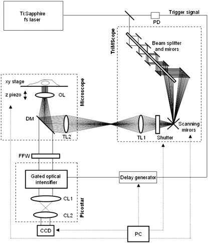
FIGURE 3.
TriM-FLIM setup. The scheme describes the optical path of the excitation source and the different components of the system. The excitation source is a two-photon Ti:Sapphire fs laser, tunable from 700 nm to 950 nm. Part of the laser is sent to a fast photodiode (PD) and the signal, which is used to trigger the gated optical intensifier, passes through a delay generator. The laser then enters the TriMScope. The laser beam goes through the combination of beam splitter and mirrors generating 64 beams which are scanned and directed into the objective lens (OL) by passing through tube lens (TL1 and TL2). The fluorescence signal from the sample is selected by a dichroic mirror (DM) and a fluorescence filter inserted into a wheel (FFW) and directed to the PicoStar constituted by a gated optical intensifier (photocathode, multichannel plates, and phosphor screen) and an optical coupling system (CL1 and CL2). The image is then acquired by a CCD camera. A PC controls the scanning mirrors, the excitation shutter, the delay generator, the CCD camera, the FFW, and the microscope (xy stage and z piezo) using IMspector software.

