Figure 2.
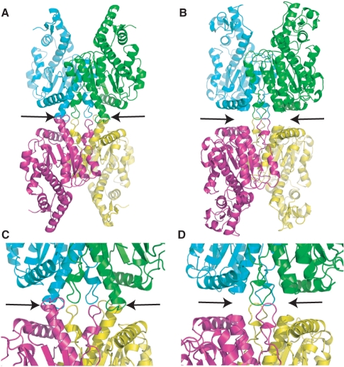
Cfr10I Tetramer. (A) Tetramer of Cfr10I with individual subunits shown in cyan, green, pink and yellow. Arrows indicate dimer–dimer contacts formed by helical extensions identified in Figure 1C. (B) Model of a SgrAI tetramer where individual subunits of SgrAI are superimposed onto individual subunits of Cfr10I in the Cfr10I tetramer. Alignments were made using the alignment provided by DALI (30), shown in Figure S1. (C) Close-up of the dimer–dimer interface of the Cfr10I tetramer. Arrows as in A. (D) Close-up of the dimer–dimer interface of the SgrAI tetramer model shown in B. Arrows as in B.

