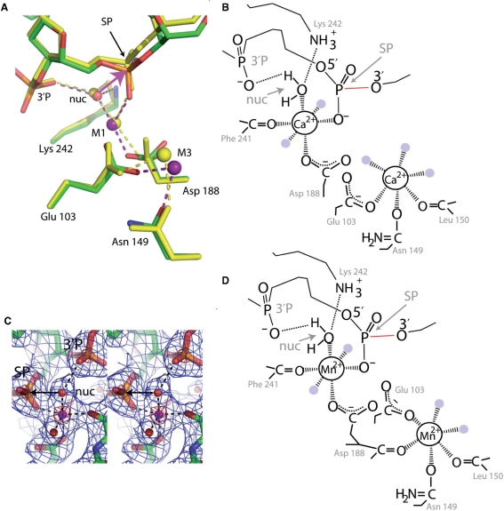
Figure 6.
Metal ion binding. (A) Superposition of Form 2 structures with Ca2+ (yellow, Ca2+ shown as yellow sphere) and Mn2+ (green, red, orange, blue, Mn2+shown as purple spheres) using the alpha carbon atoms of residues 103, 149, 188 and 242. SP, phosphate of the scissile phosphodiester bond, 3′P, phosphate 3′ of SP, nuc, water molecule positioned for in-line attack on the SP, M1 and M2, metal ion binding sites, pink arrow, direction of nucleophilic attack, red line, scissile bond. (B) Schematic of the interactions around the two Ca2+ of the Form 2 Ca2+ bound structure of SgrAI, shown in Figure 6A. Dashed lines indicate ligation to the Ca2+ ions. Some water molecules ligated to the Ca2+ are shown as light blue circles. (C) Stereo diagram of the electron density around an M1 Mn2+ ion in the Form 2 Mn2+ bound structure of SgrAI. Simulated annealing omit 2Fo−Fc electron density shown in blue (1σ) and red (8σ). SP, 3′P, nuc defined as in Figure 6A, arrow, direction of nucleophilic attack. The Mn2+ is shown as a pink sphere and ligated water molecules as red spheres. Ligations to the Mn2+ are shown as dashed lines. (D) Schematic of the interactions around the Mn2+ ions of the Form 2 Mn2+ bound structure of SgrAI, shown in Figure 6A. Dashed lines indicate ligation to the Mn2+ ions. Water molecules ligated to the Mn2+ ions are shown as light blue circles.

